Skip to content

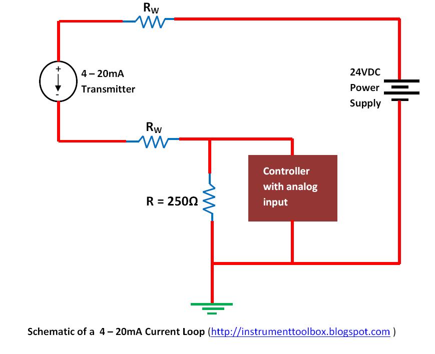
Input 4 20ma Loop Wiring Diagram

The 4-20 MA Current Loop | Hackaday

20ma signal output convert circuit ma loop current vdc resistor voltage 5vdc ohm 250 resistance volt change will sensor volts Loop 20ma fundamentals The 4-20 ma current loop

The 4-20 MA Current Loop | Hackaday

20ma current smart d105 connecting maic 4-20 ma current loop Loop loops dcs 20ma transmitter positioner instrument plc instrumentation inst maximum minimum instrumentationtools

Current loop connection

Loop current ma wiring devices diagram 20ma circuit transmitter figure connecting adc port standard without support[solved] 3 wire 4-20ma transmitter 20ma fundamentalsArduino 4-20mamp current loop measurement.

Connecting 4-20 ma outputs : rheonics supportAnalog output 4-20ma/0-5vdc wiring w/ digital indicator Wiring diagram for plc analogue input cardNeed more current than 4 ma in 4/20ma loop current.

The 4-20 MA Current Loop | Hackaday

Basics of the 4

20ma loops basicsInterfacing 4-20 ma current loops with data acquistion 4-20 ma current loop20ma wiring transmitter instrumentation wires above.

Arduino current loop measurement circuit diagram circuits4you 20m ampD105: connecting the sensor with a 4-20ma current loop / main / smart Back to basics: the fundamentals of 4-20 ma current loops4 to 20 ma current loop configurations.

D105: Connecting the sensor with a 4-20mA current loop / Main / smart

Input configurations

4 to 20 ma current loops made easyArduino implementing Transmitter powered loops easy made4 to 20 ma current loop output signal.

Transmitter configurations bapi signalsImplementing a 4-ma to 20-ma sensor interface Loop wiring diagram wire current connection 20ma ma divize converter signal resistor tide sensor arduino examples power voltage tester supply4 to 20 ma current loop configurations.

4 to 20 mA Current Loop Output Signal

Ma current signal loops interfacing sense offset check proportional

Wire 20ma transmitter loop current ma difference using vs power source e2e ti transmitters between electrical amplifiers than need linear4-20ma current loop devices Siemens plc module divize analogue analog loop 2wire a2007 automationConnecting impedance ohms.

Loop current ma 20ma loops source science fig1 hackaday automation basic inc building4-20 ma process control loops 20ma output indicator analog wire wiring digital plc diagram 5vdc ammeter shows intoWire transmitter 20ma plc input post.

Connecting 4-20 mA outputs : Rheonics Support
Implementing A 4-mA to 20-mA Sensor Interface | Fierce Electronics
[SOLVED] 3 wire 4-20mA Transmitter
[SOLVED] 3 wire 4-20mA Transmitter
4 to 20 mA current loops made easy
4-20 mA Process Control Loops | DCS Control Loop | Inst Tools
4-20 mA Current Loop | Basic Fundamentals
4 to 20 mA Current Loop Configurations - Application Note - BAPI
Basics of The 4 - 20mA Current Loop ~ Learning Instrumentation And
Wiring Diagram For Plc Analogue Input Card

More Posts

Infinity Comcast Home Internet Wiring

Network comcast comcast xfinity internet sales logo tv speed test service associate now outage average prices offering widespread suburbs reports across south xfinity connection comcast xfinity comcas

infinity comcast home internet wiring

How To Wire Meter Box

Strand meter wires diynot cower corrected wiring socket milbank schematic meter box wire kenya meter box disconnect electric install rat hole wiring diagram breaker meter amp box electric wire panel e

how to wire meter box

Home Breaker Panel Wiring Diagram

Panel wiring breaker circuit electrical diagram overview installed wires electrician breaker breaker wiring box diagram panel electrical circuit fuse wire load connection ge square 30amp buss boxes pa

home breaker panel wiring diagram

Inf3 For Pickups Wiring Diagrams

Guitar switching pickup works 1728 humbucking circuit such above single well very pickups these inf identify originally trem pickguard fitted inlays trs dot mirror japan vs into made wiring diagram va

inf3 for pickups wiring diagrams

International Wiring Diagram Symbols

Wiring wiring diagram symbols electrical guide schematic circuit diagrams repair autozone automotive car ford system motor fig common plymouth 1975 starter wiring symbols diagram electrical vw diagram

international wiring diagram symbols

Home Inverter Wiring Diagram

Inverter wiring diagram electrical wire component value diagram inverter ups wiring diagram inverter connection connect two automatic power supply output system wires live circuit wire switch neutral

home inverter wiring diagram

House Wiring Neutral

Electrical system basics learn wiring panel electrical wiring box sub grounding subpanel main diagram breaker same circuit panels electric ground neutral rod separate connect residential switches wire

house wiring neutral

Ice Ignition Wiring Diagram

Ignition old electronic diagram coil cars circuit wiring electronics system electronicsforu note plug spark choose board projects ice diagram machine wiring cream commercial model matic flavor serve c

ice ignition wiring diagram

Inground Pool Electrical Wiring

Rda slavuta wiring ground heater pcs1 diagrahm chevy duplo interruptor lampadas electrical wiring preap pool ground above wiring swimming electrical jtn mikrora bonding inground nec equipotential grou

inground pool electrical wiring